How to Choose Ground Screws for Your Project?
Ground Screws can look simple on a drawing: steel shafts, helical plates, and a frame above grade. But choosing them well starts below the surface. Soil strength, groundwater, frost depth, corrosion exposure, and structural loads all affect whether a screw can perform as intended. A neat product specification cannot replace a site assessment.
The demand for dependable foundations is growing. The IEA’s Renewables 2024 report states that global renewable capacity additions rose nearly 50% in 2023, reaching almost 510 GW; solar PV made up about three-quarters of that growth. Those figures are not ground-screw sales data, but they show why foundation choices matter across expanding projects. Small details count. A wet clay layer or a shallow rock shelf can change installation plans quickly.
This guide explains how to compare screw diameter, shaft length, steel protection, load ratings, and installation methods. It also considers when a geotechnical investigation or pull-out test is sensible. There is no verified source for a named ground-screw specialist’s quotation in the material provided, so I will not invent one. That gap matters. Real projects deserve traceable advice, not a polished quote with uncertain origins. The right choice may still involve trade-offs; site conditions rarely fit a perfect chart.
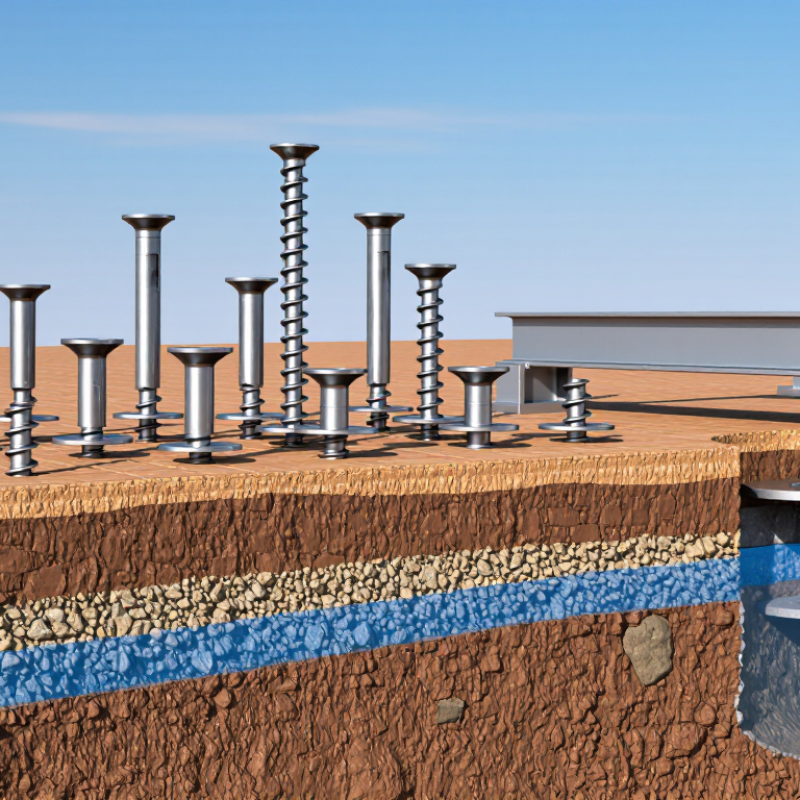
Define Project Loads Using ASCE 7 and Applicable Building-Code Criteria
Choosing ground screws starts with the forces the foundation must resist, not with screw dimensions. Under ASCE 7, identify dead, live, roof, snow, wind, and seismic loads relevant to the structure. A canopy may seem light, but its exposed roof can create substantial uplift. So can gusty wind.
Use the load combinations required by the locally adopted building code, including applicable amendments. The governing edition matters. Account for site conditions such as wind exposure, building height, risk category, and snow drifting where relevant. Small details matter. A roof edge near a taller wall, for example, may experience different snow or wind demands than an open, unobstructed site.
Then translate those building loads into forces at each screw: compression, uplift, lateral load, and moment. Check the load path from roof framing through posts and connections to the ground screws. Avoid comparing a single advertised capacity directly with total building load; spacing, eccentricity, soil conditions, and group effects can change the demand on individual supports. A tidy calculation can still miss a site-specific issue. Verify soil assumptions with suitable geotechnical information, and have a qualified design professional confirm the loads, combinations, and foundation details for the project.
Classify Site Soil with ASTM D2487 and Record Groundwater Conditions
How to Choose Ground Screws for Your Project?
Classify Site Soil with ASTM D2487 and Record Groundwater Conditions
Ground screw performance depends on what lies below the surface. A garden test hole may reveal topsoil, but not the dense layers that resist uplift. Collect representative samples at several proposed installation points and depths. Note color, grain size, moisture, and any fill, roots, or buried debris. Small details matter.
Use appropriate laboratory results, including grain-size distribution and Atterberg limits where needed, to classify soil under ASTM D2487. This system groups soils by engineering properties; it does not, by itself, confirm that a screw will meet design loads. Keep sample locations and depths traceable. Field descriptions help, but visual guesses can be wrong. That part is easy to overlook.
Record groundwater depth, the date, and the conditions observed during drilling or excavation. Water levels may change seasonally, and perched water can appear above the main groundwater table. A dry hole on one visit is not proof of consistently dry ground. Include seepage, softened soil, and recent rainfall in your notes. These observations help an engineer assess corrosion exposure, installation behavior, and suitable embedment. If conditions vary across the site, investigate each distinct area rather than relying on one convenient test location.
How to Choose Ground Screws for Your Project? - Classify Site Soil with ASTM D2487 and Record Groundwater Conditions
Note: These are illustrative site records, not project design values. ASTM D2487 classification should be based on representative samples and the required laboratory procedures, including particle-size distribution and Atterberg limits where applicable. Record groundwater depth relative to a stated ground-level datum, together with the date, measurement method, and observation time; a single reading may not represent seasonal high groundwater. Ground-screw selection and capacity require project-specific geotechnical assessment and verification.
Select Screw Diameter and Embedment from Site-Specific Load Tests
How to Choose Ground Screws for Your Project?
Select Screw Diameter and Embedment from Site-Specific Load Tests
Choose diameter and embedment from the loads your site can actually support, not from a generic soil label. Start with the required compression, uplift, and lateral loads. Then investigate the ground where the screws will go. A wet corner, loose fill, or buried topsoil can change the result over just a few metres. Small differences matter.
Plan field tests at representative locations and proposed embedment depths. ASTM D1143/D1143M covers axial compression testing; ASTM D3689/D3689M covers tension; and ASTM D3966/D3966M covers lateral loading. Ask for a report showing the applied loads, movement, soil conditions, and test setup. Use its load-displacement curves to compare screw sizes and depths against the project’s design loads. Installation torque can help track consistency, but use it as a capacity estimate only when a site- and system-specific correlation has been validated.
One test is not a map. Test near changes in slope, drainage, or fill, and investigate results that vary sharply. A screw that performs well at one location may not suit the whole site. If the tested embedment is insufficient, retest a deeper option rather than assuming a larger diameter alone will solve the problem. Keep the test records with the design calculations so the selected dimensions have a clear, reviewable basis.
How to Choose Ground Screws for Your Project?
Select screw diameter and embedment using site-specific load tests.
The chart compares example peak axial compression loads for different screw diameters and embedment depths. In practice, use load-test results from the project site and apply the design factors required by local standards. Values shown are illustrative only, not measured site data.
Check Frost Depth and Corrosion Protection Against ISO 1461 Requirements
Ground screws must extend beyond the frost-active soil zone, but frost depth is local. Use a geotechnical report or local design data, not a rule of thumb. ASCE 32-01 uses air-freezing index and mean annual temperature to inform frost-protected foundation design. A site report showing 1.2 metres of frost penetration, for example, signals that the screw’s load-bearing element may need to sit deeper. The final embedment still depends on soil strength, loads, and heave risk. Frost varies by site.
Corrosion protection needs an equally careful check. ISO 1461:2022 specifies coating thickness and testing for hot-dip galvanized steel articles; for steel over 6 millimetres thick, it sets an 85-micrometre average minimum and a 70-micrometre local minimum. Check the screw’s steel thickness and inspection records against the relevant ISO table. But coating thickness alone cannot predict service life in aggressive soil. Soil moisture, salts, acidity, and drainage matter. A practical review compares the galvanizing certificate with the geotechnical report and asks whether added protection or corrosion allowance is needed. I would not treat “galvanized” as a complete durability assessment. A small gap in the evidence can become a costly surprise underground.
Verify Installation Torque and Capacity with Manufacturer-Tested Data
How to Choose Ground Screws for Your Project?
Verify Installation Torque and Capacity with Manufacturer-Tested Data
Ground screw selection should begin with the loads your structure must carry and the soil conditions on site. Ask for manufacturer-tested data showing the screw dimensions, installation method, and soil type used. Check whether the tests report both installation torque and load capacity. These values are related, but they are not interchangeable.
Look closely at the torque range linked to the stated capacity. A crew can record torque with a calibrated tool, then compare readings across the installation. Still, one reading cannot describe every ground condition. Wet clay, loose fill, or a buried stone can change resistance within a few feet. That matters.
Request test reports for configurations that resemble your project, including embedment depth and connection details. Confirm how the manufacturer defines capacity, and whether the reported value is an ultimate load or an allowable working load. Do not treat a test result as a site guarantee. If the soil differs, pause and seek project-specific engineering advice. Keep installation records, including screw location, depth, and final torque. They may reveal patterns later, though field notes are not perfect.
