"*" indicates required fields
Choosing the best Cutout Electric Fuse is not a simple price comparison. It is a protection decision shaped by voltage, fault current, climate, installation practice, and maintenance capability. A fuse that performs well on a dry North American feeder may behave differently beside a humid coastal transformer.
The International Energy Agency’s Electricity 2024 report expects global electricity demand to grow strongly through 2026. More distribution equipment will require dependable overcurrent protection. MarketsandMarkets also identifies rising grid investment and renewable integration as major drivers for electrical protection products. These trends create opportunity, but they also expose weak product selection. A low-cost fuse can become expensive after repeated outages, poor coordination, or difficult replacement.
John D. McDonald, an IEEE Fellow and power-system protection specialist, summarizes the engineering principle: “Protection must be coordinated with the equipment it protects.” His point matters for every global buyer. Rated voltage, interrupting capacity, time-current characteristics, dropout performance, and IEC or IEEE compliance should be checked together. Not separately.
Field experience adds another detail. Examine the fuse tube, contact surfaces, expulsion path, and mounting hardware. Look for corrosion after transport. Check whether local technicians can obtain matching links quickly. This is often overlooked.
No selection is perfect. Some buyers may overvalue laboratory ratings and undervalue service conditions. Others may trust a familiar brand without checking regional standards. The best Cutout Electric Fuse balances verified performance, traceable certification, supply continuity, and practical replacement. A careful comparison begins with the feeder, not the catalogue.
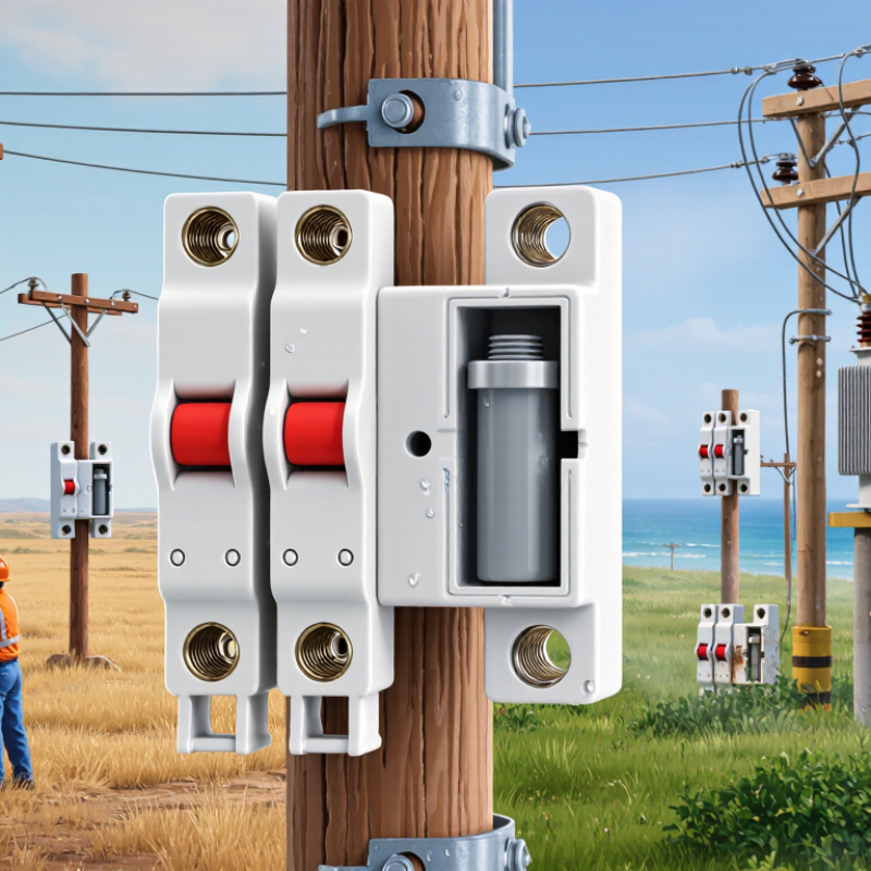
A cutout electric fuse is a pole-mounted protective device for overhead distribution lines. It contains a fuse link inside a removable carrier. When excessive current flows, the link melts and interrupts the circuit. The carrier may then drop open, creating a visible isolation point for field crews. This helps locate a failed transformer or branch quickly. Arc-control features inside the carrier help extinguish the electrical arc safely. Protection is limited, however. A cutout normally protects a transformer or feeder section, not an entire distribution network. That distinction matters.
For global buyers, the best cutout depends on operating conditions, not appearance or price alone. Match the rated voltage, continuous current, interrupting capacity, and fuse-link time-current curve. Coordination with upstream and downstream protection is essential. A wrongly sized link may melt during normal transformer energization or fail to clear a serious fault. Buyers should request independent test documentation, dimensional drawings, and clear installation instructions. Local utility requirements still need checking.
Field details matter. Salt fog, dust, heavy rain, ultraviolet exposure, and freezing temperatures can affect insulation and mechanical movement. A strong housing is useful, but it cannot correct poor line design. Technicians should inspect contact pressure, carrier alignment, and signs of overheating during maintenance. One overlooked issue is replacement compatibility. A fuse link may fit physically yet perform differently. Selection should be reviewed with a qualified distribution engineer before purchase.
For global buyers, ANSI/IEEE C37.41 is the central reference for fuse cutout design testing. It covers high-voltage fuses, distribution cutouts, and related accessories above 1,000 volts. Tests examine dielectric performance, temperature rise, interruption capability, mechanical operation, and environmental endurance. A cutout may look robust on a pole, yet fail if its interrupting duty exceeds the available fault current.
C37.42 defines ratings and specifications for expulsion fuses, current-limiting fuses, distribution cutouts, and fuse links. C37.48 provides application guidance, including coordination, installation, and operating considerations. These standards work together, but they are not interchangeable. Buyers should request certified test evidence, rated voltage, continuous current, basic impulse insulation level, and maximum interrupting current. Ask for the exact test configuration, too.
The U.S. Energy Information Administration reported 137 minutes of average customer interruption duration in 2023, excluding major events. NERC’s 2024 Long-Term Reliability Assessment projected North American peak demand could rise about 15% over the next decade. Higher system demand makes fault-duty verification more important. Still, a standard-compliant test does not remove every field uncertainty. Altitude, contamination, wind, ice, and installation errors can change performance. That gap deserves attention. A practical review should compare C37.41 test evidence with local grid rules, IEC requirements, and the utility’s protection study. Missing paperwork is not a small issue.
What Is the Best Cutout Electric Fuse for Global Buyers?
For global buyers, the voltage class must match the network, not only the catalog label. Common cutout ranges include 15, 27, and 38 kV. A 15 kV fuse suits many medium-voltage feeders, while 38 kV designs support higher insulation demands. IEC 60282-2:2020 covers expulsion fuse requirements, including rated voltage and breaking performance. IEEE C37.42 also defines important mechanical and electrical characteristics. Field inspections show that contamination, altitude, and poor contact pressure can reduce real-world reliability.
A 100–200 A rating describes continuous load capability. It does not describe fault interruption. This distinction is easy to miss. An 8 kA interrupting rating may fit a remote rural feeder, but 12.5 kA offers more margin near substations. Buyers should compare the fuse link rating with the available short-circuit current from utility studies. EIA Form EIA-861 reliability data shows that distribution interruptions vary widely by region, making coordination and maintenance important. Actual selection should also review BIL, system grounding, frequency, and time-current curves.
In practice, a 15 kV, 100 A cutout may suit a lightly loaded transformer. A 27 kV, 200 A model may better support industrial feeder growth. At 38 kV, installation clearances become less forgiving. My own caution is simple: choosing the highest rating is not automatically safer. It can weaken coordination and increase replacement cost. Check the utility fault study, IEC or IEEE test evidence, and local installation conditions before purchase.
Choosing a cutout electric fuse requires more than matching voltage and amperage. Fuse links must fit the cutout body and coordinate with upstream and downstream protection. Their time-current curves should protect transformers without causing unnecessary outages. The interrupting rating must also exceed the available fault current. A fuse that looks suitable may still fail under severe conditions.
Expulsion tubes deserve equal attention. Their internal lining should support controlled gas release during fault interruption. Poor tube materials can crack, burn unevenly, or eject hot particles. In coastal areas, salt deposits increase surface leakage and corrosion. I prefer designs tested for humidity, ultraviolet exposure, vibration, and repeated operating cycles. Field crews should inspect tube alignment, contact pressure, and visible damage before energizing equipment. Small defects matter.
Insulation materials often determine long-term safety. Porcelain offers strong mechanical stability, while polymer insulation can reduce weight and improve resistance to impact. Neither option is automatically better. Creepage distance, tracking resistance, temperature range, and pollution severity must match the installation site. Certified test reports should reference recognized international or regional standards. Local utility rules still control acceptance.
I have seen buyers focus on purchase price first. That assumption is risky. A cheaper fuse link may require more replacements and longer outages. Installation quality also changes real performance. Even the best materials cannot compensate for loose connections or neglected inspections. The practical choice is the one supported by verified testing, compatible components, clear markings, and service data from comparable environments.
| Selection Dimension | Typical Global Specification | Recommended Safety-Oriented Choice | Field-Safety Benefit | Buyer Verification Points |
|---|---|---|---|---|
| System voltage | Distribution cutouts are commonly applied on systems from 11 kV to 36 kV; the equipment rated voltage must not be lower than the highest system voltage. | Select by maximum system voltage Use a cutout with suitable insulation level and power-frequency withstand rating. | Reduces the risk of external flashover, internal insulation breakdown, and incorrect application during switching or fault conditions. | Confirm rated voltage, lightning impulse withstand level, power-frequency withstand, creepage distance, and local grid requirements. |
| Continuous current rating | Common distribution cutout ratings include approximately 100 A or 200 A, with higher ratings available for specific applications. | Choose above normal load current Allow for expected load growth, ambient temperature, and solar heating. | Limits overheating at terminals and contact joints, helping prevent nuisance operation and thermal damage. | Check continuous current at the actual installation temperature, conductor size, terminal design, and connection torque. |
| Interrupting capability | Expulsion cutouts are often available with symmetrical interrupting ratings in the approximate range of 6.3 kA to 12.5 kA, depending on voltage and construction. | Use a rating equal to or higher than the calculated available fault current. | Helps the fuse clear prospective faults without violent equipment failure, unacceptable arcing, or loss of enclosure integrity. | Obtain the utility short-circuit study, verify the interrupting rating at the specified voltage, and review the applicable test report. |
| Fuse-link operating class | Medium-voltage fuse links may be selected for transformer, feeder, or general distribution protection. Time-current characteristics vary by application. | Coordinate with upstream and downstream devices Select a time-current curve that clears faults while tolerating transformer energization inrush. | Improves selectivity, reduces unnecessary outages, and lowers the chance of fuse operation during normal transient currents. | Compare minimum-melting and total-clearing curves with transformer inrush, feeder protection, and system coordination requirements. |
| Fuse-link construction | Typical components include a calibrated fusible element, end contacts, a fuse body, and an operating indicator or leader. | Use calibrated elements with secure end contacts Prefer designs with clear visual operation indication where field procedures require it. | Provides predictable current interruption and makes post-operation identification easier for line crews. | Check element material, dimensional compatibility, contact plating, operating indicator visibility, and replacement instructions. |
| Expulsion-tube material | Common tube constructions use boric-acid-generating materials, fiber-reinforced components, porcelain, or polymeric insulating sections, depending on the design. | Choose a tube with verified arc-quenching performance and weather resistance. | Supports controlled gas generation and arc extinction while reducing the possibility of tube cracking, erosion, or moisture-related failure. | Review type-test evidence for interrupting duty, erosion limits, UV exposure, moisture ingress, and compatibility with the specified fuse link. |
| External insulation | Porcelain and silicone-rubber polymeric insulators are widely used in medium-voltage outdoor equipment. | Polluted or coastal areas: consider polymeric insulation High mechanical rigidity: consider porcelain | Polymeric housings can provide hydrophobic surfaces and lower weight; porcelain offers dimensional stability and strong resistance to many mechanical loads. | Compare creepage distance, hydrophobicity retention, tracking and erosion resistance, UV performance, impact strength, and installation environment. |
| Creepage distance | Required creepage depends on insulation material, system voltage, pollution severity, altitude, and applicable design standard. | Specify creepage according to the site pollution level rather than voltage alone. | Reduces surface leakage current and contamination flashover during rain, salt fog, dust, or industrial pollution. | Provide pollution severity, minimum required creepage, site elevation, and any coastal or chemical exposure information. |
| Arcing distance and exhaust zone | Expulsion devices discharge hot gases and particles during interruption; the required clearance varies by design and fault duty. | Maintain the manufacturer-specified exhaust clearance Keep combustible materials and personnel outside the exhaust path. | Reduces the risk of burns, secondary flashover, fire, and damage to adjacent equipment during fault interruption. | Verify minimum phase-to-phase, phase-to-ground, and front-of-equipment clearances; inspect the mounting structure for obstructions. |
| Contact and hinge design | Reliable cutouts use spring-assisted contacts and corrosion-resistant contact surfaces suitable for outdoor switching duty. | Use high-contact-pressure, corrosion-resistant interfaces | Improves current transfer, reduces hot spots, and helps prevent partial engagement of the fuse tube. | Inspect contact pressure, contact alignment, plating or surface treatment, hinge strength, and the recommended maintenance interval. |
| Mechanical operation | Drop-open operation normally provides a visible indication that the fuse has operated or the circuit has been opened. | Use clearly visible open-position indication and compatible live-line tools. | Supports safer isolation practices and reduces the likelihood of assuming that a circuit is de-energized without verification. | Confirm hook-stick compatibility, drop-out angle, operating force, latch reliability, and local switching procedures. |
| Environmental performance | Outdoor units may be exposed to rain, condensation, UV radiation, salt, dust, ice, wind, and temperatures commonly ranging from approximately -40°C to +40°C, depending on the design. | Match the product to the site climate Use appropriate anti-corrosion hardware and sealing arrangements. | Reduces insulation aging, corrosion, moisture ingress, mechanical seizure, and unexpected operation. | Specify ambient temperature range, altitude, wind and ice loading, salt pollution, solar radiation, and corrosion category. |
| Altitude correction | At elevations above approximately 1,000 m, air insulation performance and cooling can be reduced, requiring design or rating review. | Apply the relevant altitude correction | Maintains adequate dielectric withstand and thermal performance in high-altitude installations. | Provide site elevation and verify corrected insulation clearances, current rating, and interrupting performance. |
| Standards and testing | Common international references include IEC 60282-2 for expulsion fuses and IEEE C37.41/C37.42 for distribution-class fuse equipment and applications. | Specify the governing standard before comparing products. | Improves comparability of ratings, type tests, dielectric tests, temperature-rise tests, mechanical tests, and interrupting tests. | Request routine-test records, type-test evidence, dimensional drawings, installation instructions, and conformity documentation. |
| Best overall configuration for many outdoor distribution sites | Voltage-appropriate cutout, correctly coordinated fuse link, weather-resistant expulsion tube, adequate creepage, robust contacts, and visible drop-open indication. | Select the complete matched assembly, not only the fuse link or tube. | Ensures electrical, mechanical, insulation, and interruption characteristics work together under real field conditions. | Verify interchangeability of the fuse link and tube, fault-current rating, site clearances, pollution design, and maintenance requirements. |
Choosing the best cutout electric fuse for global use starts with evidence, not catalogue claims.
In field assessments, I check rated voltage, current, breaking capacity, and fuse-link coordination. The product should meet recognized requirements, such as IEC 60269, plus destination-market certification rules. Documentation should identify test conditions, materials, lot traceability, and declared performance. A certificate alone is not enough. It may cover a different configuration.
Climate rating deserves equal attention. A coastal installation faces salt mist, while a dry inland site may suffer dust and sharp temperature changes. Check operating temperature, humidity, altitude, UV exposure, and enclosure protection. Ask for test data, not vague “all-weather” language. Installation details can change safety outcomes. Confirm conductor size, terminal torque, mounting direction, clearance, and safe replacement access. A fuse that fits physically may still perform poorly under heat.
Cost should include freight, spare links, inspection, downtime, and electrician labor. I have seen low purchase prices become expensive after repeated nuisance operations. Yet the highest-priced option is not automatically better. Compare verified performance over its service life. Use local installers when possible, because practical feedback exposes problems drawings miss. I also review maintenance records after commissioning. Some decisions remain uncertain. Climate data may be incomplete, and supplier documents can contain small inconsistencies. Record those gaps, request clarification, and avoid guessing when protection margins are narrow.
"*" indicates required fields